Convert world to screen coordinates and vice versa in WebGL

In this blog post, we will discuss different coordinate systems in WebGL and implement two functions in TypeScript. The first function will convert the world coordinates to screen coordinates (aka canvas coordinates) and the second one will do the opposite — convert screen coordinates to world coordinates. This is a quite common task. Normally, we construct a scene with different objects in world coordinates. Such coordinates can be e.g. time, meter, temperature or everything what you want. In WebGL, everything gets rendered into a canvas. Often you need to know for a given point in world coordinates what is the position of that point in 2D — on the screen (canvas) in pixel coordinates. The opposite is also true. E.g. you interact with mouse on a visual canvas and would like to know the object’s world coordinate below the mouse cursor. In this blog post, we will only implement the mentioned conversion formulas in the 2D space.
If you look at the picture above, you will see that everything starts with local coordinates. When you’re creating a model of 2D / 3D objects, you create them at the origin (0,0,0). The model can be easily built at this point. Local coordinates are the coordinates of your object relative to its local origin.
In the real life, different 2D / 3D objects are placed somewhere in the world space at different coordinates. The coordinates of your objects are transformed from local to world coordinates. This happens with the help of translation, scaling and rotation. Well, there is skewing too, but it’s a rare transformation. Every transformation can be represented as a matrix. There are a lot of resources about transformation matrices. E.g. a simple introduction to 2D transformations. Such transformations for an object can be multiplied and build a final transformation which is called the model matrix. As already said, all particular objects are normally grouped hierarchically within a scene (often called a scene graph too). You can read a nice explanation for such structure on WebGLFundamentals. Of course, the scene as a whole can be translated, scaled and rotated as well. Every transformation on the scene gets recursively applied to all objects in this scene. Just two examples from one of my projects at Swiss Federal Railways (SBB) how the scenes in world coordinates can look like (just two cropped scenes’ parts).

X-coordinate in this scene is defined as numeric index 0, … N. There is a grey vertical line per index labeled in green. Y-coordinate is defined in time intervals. The objects in the scene are train routes. The second scene is defined in pixel (the same unit as screen coordinates), but the origin and axes of the scene (red color) are different from the origin and axes of the HMTL canvas (blue color). The objects in the scene are railway elements on the track network such as edges, signals, track numbers, points, etc.

The next stage is a view space. The view space is the result of transforming the world-space coordinates to view coordinates that are in front of the user’s view. The view space is the space as seen from the camera’s point of view. Such transformation means that the camera is moving around the world. Well, in fact, the world is moving, and the camera is still. A matrix describing such transformation considers amongst others a camera’s position and view direction. Per default, the camera is positioned at the point (0,0,0) where the camera is looking down the z-axis. In this blog post, we will take a default position. That means, the view matrix is an identity matrix and can be skipped entirely.
In a WebGL program, data is typically uploaded to the GPU with its own coordinate system. The coordinates in such coordinate system are restricted to (1,1,1) and (-1,-1,-1). The x, y and z coordinates of each vertex should be between -1.0 and 1.0. Coordinates outside this range will not be visible. Such coordinates are normally called clip coordinates.

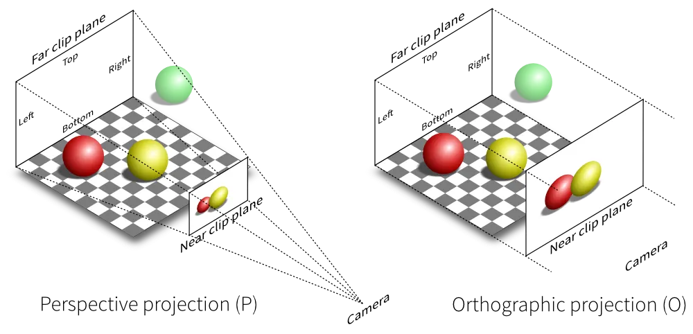
They are often called normalized device coordinates (NDC) too. Such coordinate system is used in vertex shader. Vertex shader is a stage in the rendering pipeline that handles the processing of individual vertices which are given then to the rasterizer (rasterizer transforms vertices to pixels on screen). Projection to clip coordinates is accomplished by using a projection matrix. There are two main projections: orthographic projection and perspective projection. An orthographic projection matrix defines a cube-like frustum box where each vertex outside this box is clipped. CAD programs normally operate with such projection. Perspective projection is normally used in games where a real life is simulated and the objects that are farther away appear much smaller. I have found one picture on Stack Overflow which demonstrates both projections at a glance.
In the last step, the clip coordinates should be transformed to screen coordinates. This process transforms the coordinates from -1.0 and 1.0 to the coordinate range defined by the visible canvas. The canvas has its own coordinate system. The upper left corner of the screen coordinate system is (0,0) and the lower right is (width,height).

The transformation occurs by the viewport method on the WebGLRenderingContext. That’s all to five different coordinate systems that are important for us. Let’s start with mathematics. Look at the first picture to this blog post please. We will define a point in the clip space as a vector C. The x coordinate is defined as Cx and the y coordinate as Cy respectively. We can convert a local coordinate to a clip coordinate with the help of model-view-projection matrix. We can also convert a world coordinate to a clip coordinate with the help of view-projection matrix or more general with the help of model-view-projection matrix because the scene itself can be transformed too (translated, scaled or rotated). We will define a point in the world space as a vector W. The x coordinate is defined as Wx and the y coordinate as Wy respectively. Furthermore, we will designate the model-view-projection matrix as P. With these designations in mind, we come to the formulas:

In the last formula, we introduced the screen coordinates as a vector S and expressed the clip coordinates by the screen coordinates according to the explained coordinate systems above. For vector and matrix math, we will use the well-known library gl-matrix. The conversion function which converts a screen point to a world point can be implemented as follows:
function convertScreenToWorldPoint(xScreen: number, yScreen: number,
                                 canvasWidth: number, canvasHeight: number,
                                 projection: mat3): [number, number] {
  const clipCoord: vec2 = vec2.fromValues(
    2.0 * xScreen / canvasWidth - 1.0,
    1.0 - 2.0 * yScreen / canvasHeight);

  const worldVec = vec2.transformMat3(
    vec2.create(),
    clipCoord,
    mat3.invert(mat3.create(), projection));

  return [worldVec[0], worldVec[1]];
}
As you see, it’s simple enough. The last formula can be paraphrased and written down in another way:

Now, let’s express the screen coordinates on the left side by the clip coordinates:

That gives us a conversion from a world point to a screen point resulting in this implementation:
function convertWorldToScreenPoint(xWorld: number, yWorld: number,
                                 canvasWidth: number, canvasHeight: number,
                                 projection: mat3): [number, number] {
  const clipCoord: vec2 = vec2.transformMat3(
    vec2.create(),
    vec2.fromValues(xWorld, yWorld),
    projection);

  const screenVec = vec2.fromValues(
    (1.0 + clipCoord[0]) * canvasWidth / 2.0,
    (1.0 - clipCoord[1]) * canvasHeight / 2.0);

  return [Math.round(screenVec[0]), Math.round(screenVec[1])];
}
As already said, in the reality, you should take all scene transformations into account. That means, the projection matrix passed to the functions is a combined matrix out of model-view-projection transformations. A simple 2D projection matrix with the given bounds and without any model-view transformations can be generated as follows (just to give an example):
function getProjection(canvasWidth: number, canvasHeight: number): mat3 {
  return mat3.projection(mat3.create(), canvasWidth, canvasHeight);
}
That’s all. Stay tuned!